

Prerequisites
Complete Xentara on Docker – Quick Start Guide first. This guide assumes you finished that guide and the system running Xentara on docker is available.
Introduction
After you complete the Xentara on Docker Quick Start, you have a licensed runtime. The TUI App on your WAGO edge device runs Xentara's signal-generator demo model. Six synthetic waveforms update live. This guide replaces that synthetic model with a model built from your own hardware. Xentara discovers the modules on your EtherCAT bus. You then browse and toggle real digital and analog I/O from the browser.
This is the full hands-on path. It is quick once the runtime is up. A later section describes two further capabilities: timed hardware round trips, and outputs driven by a live MQTT feed. The companion repository has the full walkthroughs for both. We tested this guide on a WAGO 752-9xxx-class edge controller with a WAGO 750-354 EtherCAT coupler.
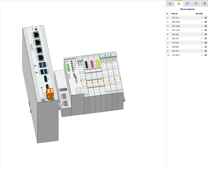
The companion repository has the compose file, the C++ control, ready-made model templates, and every screenshot in this guide: github.com/WagoAlex/wago-xentara-example
What You Need
This guide assumes you completed the Docker Quick Start. The xentara/xentara-tryout stack must run on your WAGO edge device, and a base license must be active (the signal-generator demo loads and runs).
You also need:
- A WAGO EtherCAT coupler (this guide uses a 750-354) with at least one I/O terminal on the bus, cabled to the controller.
- Two licensed skills: CoE (the EtherCAT driver) and CPP (the C++ control host). Check that your licenses.json skills array lists both with a current expiry date. Without CoE, the bus does not start. Without CPP, the control does not load.
- The xentara/xentara-build image. Use it to compile the C++ control. The Xentara SDK does not need to touch the host.
From the Signal Generator to Real Hardware
You deployed the xentara/xentara-tryout stack on your WAGO edge controller through Portainer. The signal-generator demo runs there, as it did in the Quick Start guide:
Stacks → Add stack → Web editor. Paste the compose file. Click Deploy the stack. Activate the node ID.
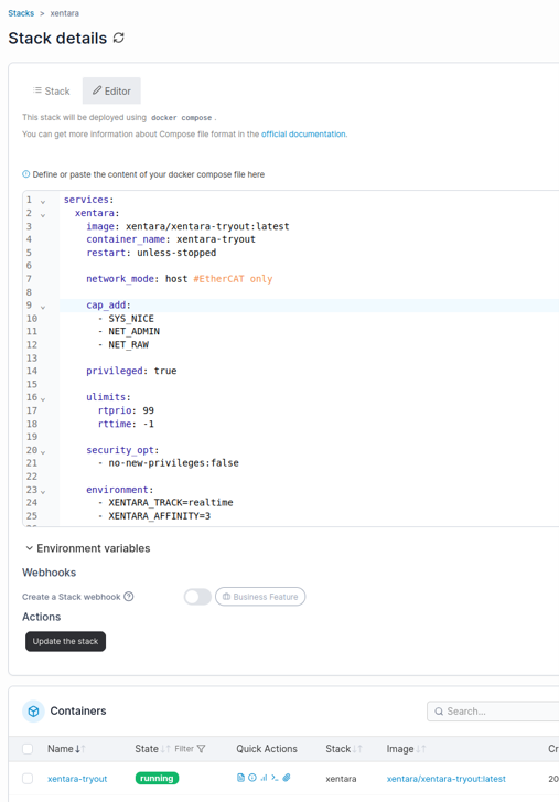
One property of this stack matters now: it runs with host networking. This lets Xentara's EtherCAT master reach a physical network port on the controller and communicate with the coupler. The deployment does not change. You point the runtime at a model discovered from your own hardware instead of the synthetic demo.
💡 A note on one step you repeat: when a step says “open the container console,” go to Containers → xentara-tryout → Console → Connect, shell /bin/bash. This opens a terminal in your browser. You do not need SSH.
Step 1: Dedicate a Network Port to EtherCAT
Xentara's EtherCAT master takes over a network interface. It sends raw Layer 2 frames on that interface. The interface must carry no IP address.
A WAGO edge device has several ports. Use this split:
- One static LAN port for management (default: https://192.168.2.17:9090 for browser access to WBM, and https://192.168.2.17:9443 for Portainer).
- One LAN port for general uplink, with DHCP.
- The EtherCAT port, with no configuration and no IPv4 address.
Verify this setup in the device's Web-Based Management (WBM) UI, under Networking / TCP-IP. Then cable the EtherCAT port to the coupler.
A link-local IPv6 address on this port is normal. Make sure it has no IPv4 address. Note the interface name. On WAGO devices this is often X11. On other devices it may be eth0 or enp3s0. You pass this name as <your-nic> in later steps.
Step 2: Build and Deploy the Control
The control is a small C++ probe. It measures the interval between its own scheduled runs, called the achieved cycle time. It publishes this value as live registers alongside your I/O. Find its source in the companion repository at control/ethercat-rtt-probe/.
Build the control inside the xentara/xentara-build image. The project's .devcontainer.json and README.md give the exact build command. The build produces libEtherCATRttProbe.so. Copy this file into the running container:
docker cp build-amd64/libEtherCATRttProbe.so \
  xentara-tryout:/home/xentara/.config/xentara/control/EtherCATRttProbe.so
On an ARM target, build for arm64 and copy the build-arm64 output instead.
Note the filename on the target: use the bare name EtherCATRttProbe.so, with no control / prefix. The model refers to a control by its bare filename. A stray path prefix is the most common reason a control loads but its step() function never runs.
Step 3: Discover Your I/O Modules
In this step, Xentara writes a model that matches your hardware. The xentara-ethercat-model-file-generator scans the live bus and creates a complete model for every terminal it finds. The scan needs exclusive use of the EtherCAT NIC.
Stop the runtime and run the generator in a throwaway container. Copy template-rtt.json from the repository onto the device, for example into ~/model/. Then run:
docker stop xentara-tryout
docker run --rm --network host --privileged \
  --cap-add NET_RAW --cap-add NET_ADMIN --cap-add SYS_NICE \
  --entrypoint bash \
  -v ~/model:/out -w /out \
  xentara/xentara-tryout:latest -lc \
  'xentara-ethercat-model-file-generator \
  -i template-rtt.json -o model.json \
  -b <your-nic> -m online -n "EtherCAT Terminal" -v'
docker start xentara-tryout
The generator prints every channel it finds: index, subindex, type, and name. This printout is your module inventory.
The #CoE.Bus:EtherCAT Terminal marker inside the template tells the generator where to place the discovered bus. The generator keeps the rest of the template, a 1 ms track and the probe wiring. As a result, model.json comes out complete and ready to run.
⚠️ Important: never open a template-*.json file directly in the workbench. This file is a generator input, not a Xentara model. It contains the literal #CoE.Bus:EtherCAT Terminal placeholder. This placeholder is valid input for the generator, but it is not valid model JSON. If you open it in the Workbench, or load it as model.json, you get the error “expected a JSON object” on that line. Always load the generated model.json file.
Two more notes:
- Addresses shift when you add, remove or move a terminal. Re-run this scan whenever the physical row changes. Discovery keeps the model correct. Do not write addresses by hand.
- The generator does not set a synchronization mode. Set the bus to free run before you load the model. Add "synchronization": {"mode": "free run"} to the @Skill.CoE.Bus object in the generated model.json. You can also set this value in the Xentara Workbench if you edit the file there.
Step 4: Load the Model
Put the generated model.json where Xentara reads it, then restart the container:
docker cp ~/model/model.json \
  xentara-tryout:/home/xentara/.config/xentara/model.json
Restart the container. Check the Logs for the message “Using model file ...” and confirm there are no errors.
If you want to inspect or edit the model in a graphical editor first, open these model.json files directly in the Xentara Workbench. The model screenshots in the companion repository were captured this way. Then copy the file into the container as shown above.
Step 5: Browse and Toggle Your I/O
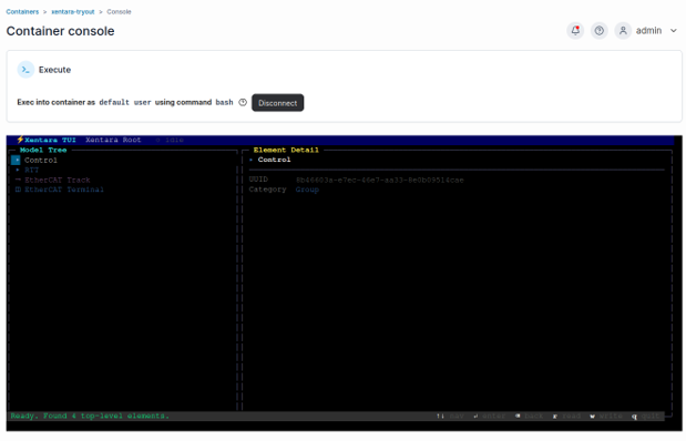
Open the container console and start the TUI App:
xentara-tui --host localhost --port 8080 --user xentara
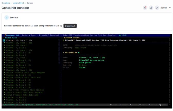
Use the arrow keys to move through the model tree. Press Enter to open an item. Open the discovered bus. You see every channel on your coupler, and each one updates live.
Read/Write inputs
Toggle a physical input and watch its channel change in the tree in real time.
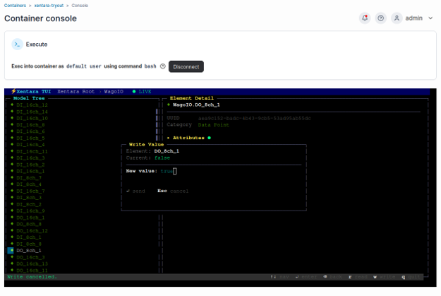
Select a digital output. Press the write key. Type "true". Press Enter. The value reaches the coupler on the next bus cycle, and the physical output switches. Type "false" to release it.
Write an analog output
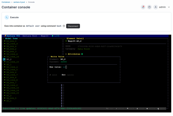
Analog channels work the same way. Select an analog output data point and write a raw count instead of true or false. This method needs no extra tooling and no code. Browsing and driving digital and analog I/O both use the same two-key gesture, in the same tree.
Read the cycle time
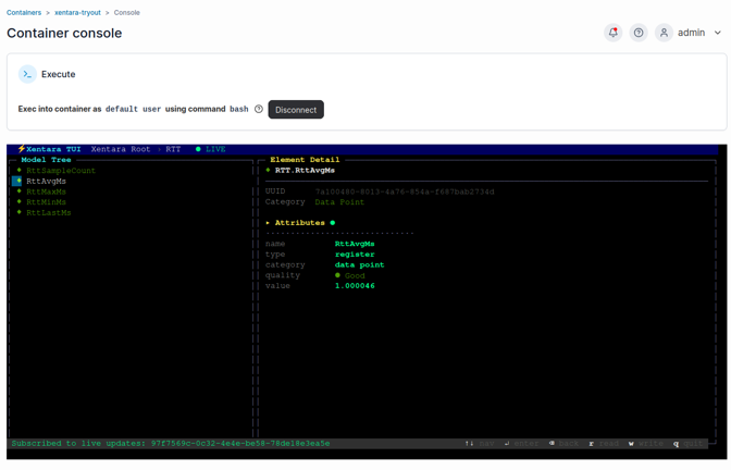
Open the RTT group for live RttAvgMs, RttMinMs, and RttMaxMs values. RttSampleCount increases every cycle. This is your proof that the pipeline runs, and does not stall on a fixed model.
💡 Physical outputs switch real hardware. Know what is wired to a channel before you toggle it.
The TUI App is not the only client that can write these values. A write is an ordinary call to Xentara's WebSocket API. Every client uses this same documented interface to communicate with the runtime. Any HMI, dashboard, or script can read and write these data points the same way the TUI App does. The TUI App is only a reference client for this API.
The companion repository includes a minimal Python client, scripts/rtt_websocket_test.py, that reads the live registers over the same connection. The full protocol is documented in the Xentara WebSocket API Specification.
Next Steps
You now have your real I/O discovered and drivable from a browser. This same foundation, a discovered EtherCAT model, a C++ control, and the WebSocket API, extends naturally. Two working examples in the companion repository build directly on what you just did:
Verified hardware round trip
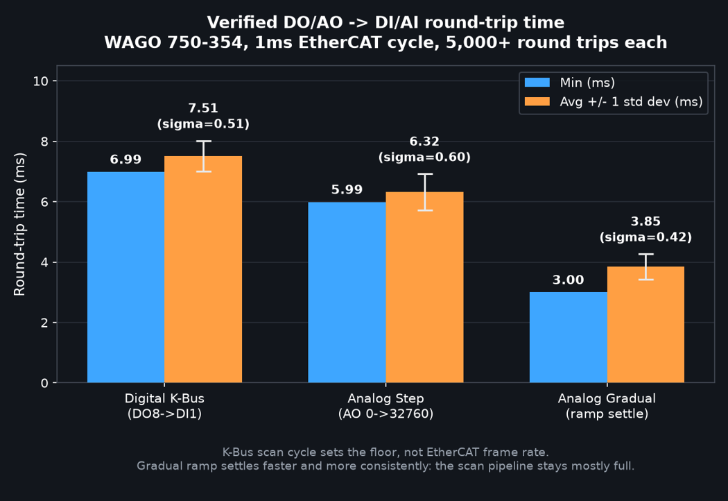
Wire a spare output back to a spare input. A control can then measure how long a value actually takes to reach physical hardware and return, not just how evenly the software cycles.
On the 750-354, this test exposed a useful fact: the round-trip floor depends on the coupler's K-Bus scan, which needs a roughly constant number of EtherCAT cycles to flush. As a result, slowing the Timer period slows real hardware response by the same proportion. The round-trip example in the repository has the full walkthrough, including wiring, control, and model.
Outputs driven by an external system
Instead of writing outputs by hand, a C++ control can for example subscribe to an MQTT topic and switch outputs from live data.
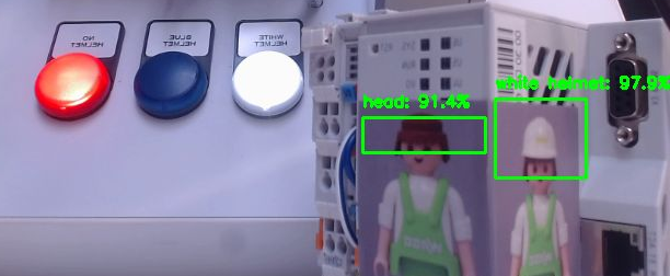
The repository's MQTT example drives three physical outputs from a wago-hailo-example Hailo-8 object-detection feed. A real camera sets real outputs, with no person in the loop. This example runs on a native Xentara install, not the tryout container, because its model needs a newer xentara-mqtt-client. The repository covers this setup from start to end.
Common Issues
- Discovery: "can't open interface." Another Xentara instance owns the NIC. Stop it first with "docker stop xentara-tryout", then run the scan again.
- Discovery: "connected devices less than configured." The coupler's state machine is out of sync. Run "xentara-ethercat-device-info --interface <your-nic>" once, then try again.
- A control loads, but its step() function never runs, and there is no error. The model's controlPath has a control / prefix. Use the bare filename instead.
- "Multiple controls are enrolled." Xentara hosts exactly one C++ control per running instance. Remove the extra @Skill.CPP.Control entry.
- An output reads true or false, but nothing physically switches. The EtherCAT addresses are stale. The model was not rediscovered against the current physical row. Regenerate the model as described in Step 3.
- Jittery cycle time. The real-time thread is being preempted. Fix XENTARA_AFFINITY, isolate that core, and use a real-time kernel.
- The TUI App reports a TLS/SSL error when it connects. The port you gave it serves the other transport (plain or encrypted) than the client expects. Connect on the web-service port your runtime actually exposes. Check your compose file and web-service configuration for this port. Do not assume a fixed port.
Conclusions
You started from the licensed runtime and the signal-generator demo of the Xentara on Docker Quick Start Guide. With this example the same container pointed at real WAGO hardware and discovered a live EtherCAT bus. Furthermore, you browsed and toggled distinct digital and analog I/O from a browser.
This is the full path from a default WAGO edge device to a running, editable industrial I/O setup, with no desktop IDE required.
The Xentara Workbench opens these model files in a graphical editor when you prefer to design models rather than generate them by hand. The TUI is a good example of how to use the build in WebSocket API and let your own applications drive everything you just did via the TUI (Terminal User Interface). The companion repository has the full source, and the round-trip and MQTT examples, for when you want to go further.